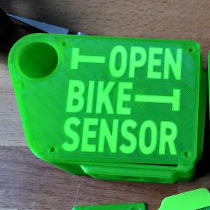
[:en]I’ve been pretty busy lately, and I spend much of my spare time on my computer on contributions to the OpenBikeSensor. [:de]Es ist schon länger still geworden hier im Blog – Derzeit arbeite ich viel am OpenBikeSensor mit. [:]
[:en]A few months ago I had a test drive on a recumbent bicycle and was instantly hooked. Suffice it to say that a few months later I am the proud owner of one myself. Being the cautious cyclist I am, my top priority especially on a recumbent is visibility. The bike is quite low, my head is around 1m of height, for me coming from an upright that’s low. Therefore visibility means adding a bikeflag. The one I went for is quite big and reflective. Nevertheless I’d still prefer some active visibility. The shop I ordered the flag from also has flaglights but basically it’s three LEDs for 70€. Knowing the material cost must be in the one-digit euros I found it hard to go for it. Especially since it is designed for bike dynamo operation requiring extra weight and extra money to be put into the bike as well. I planned on using battery operated lights already in my possesion so I don’t need dynamo equipement or cabling.
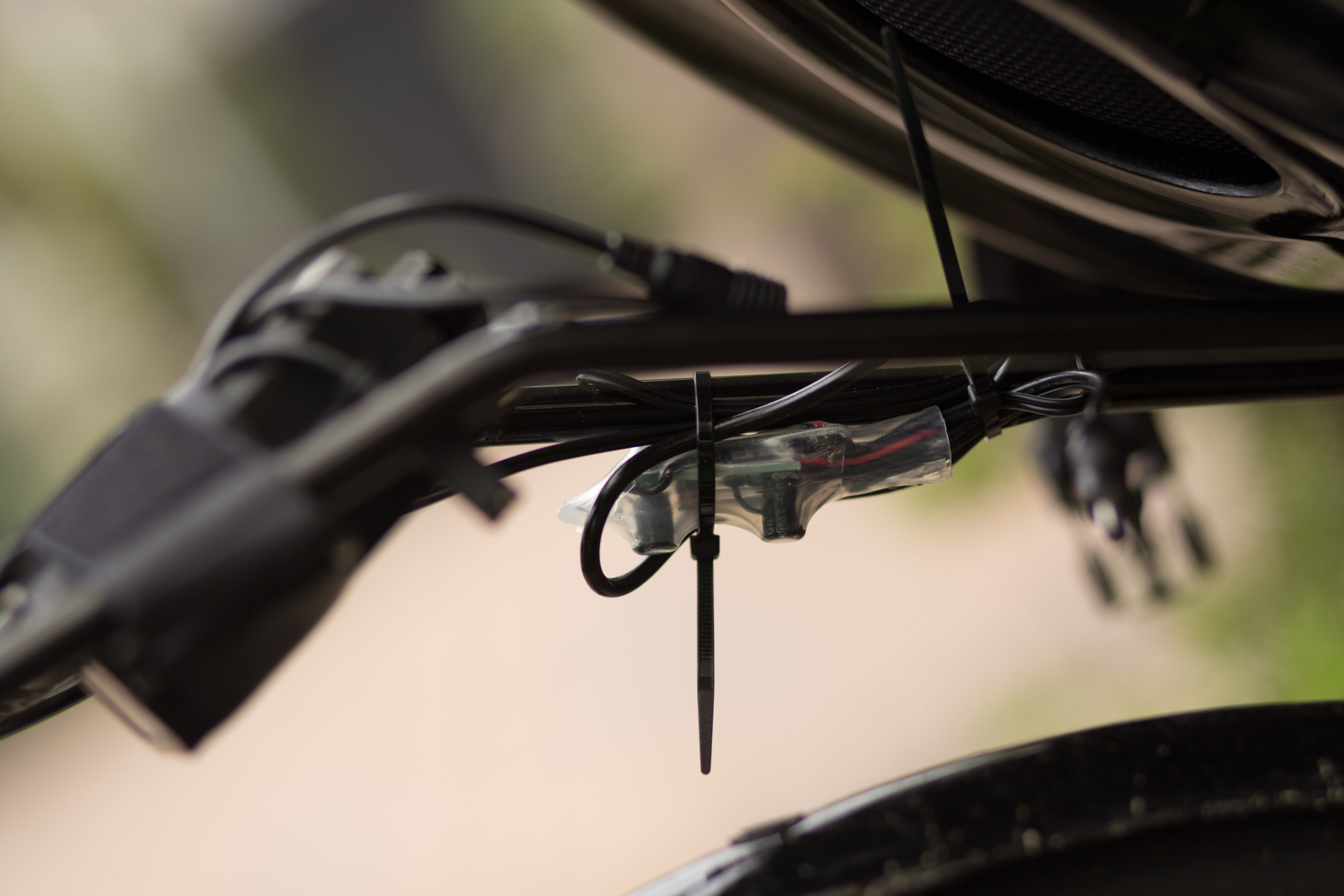
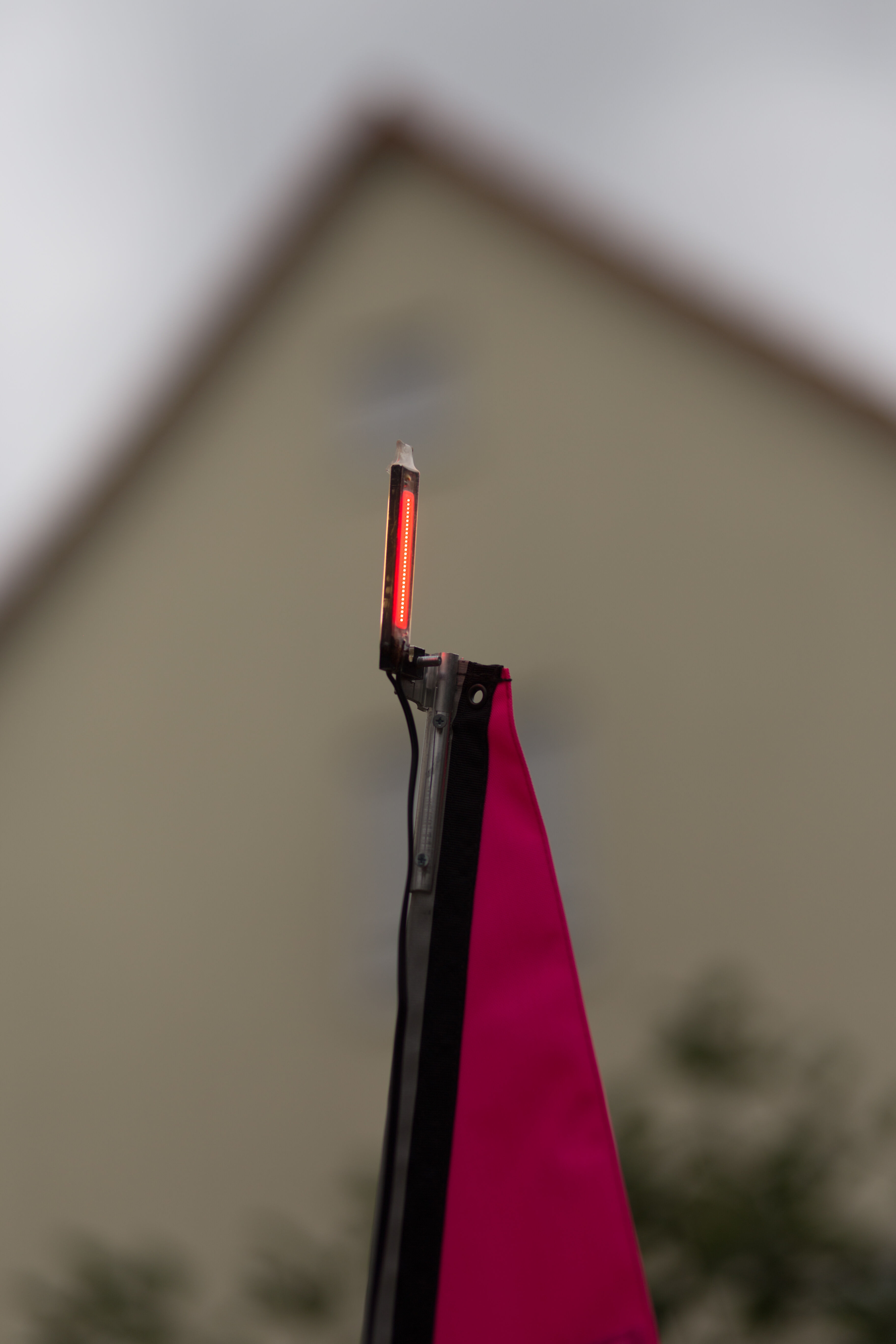
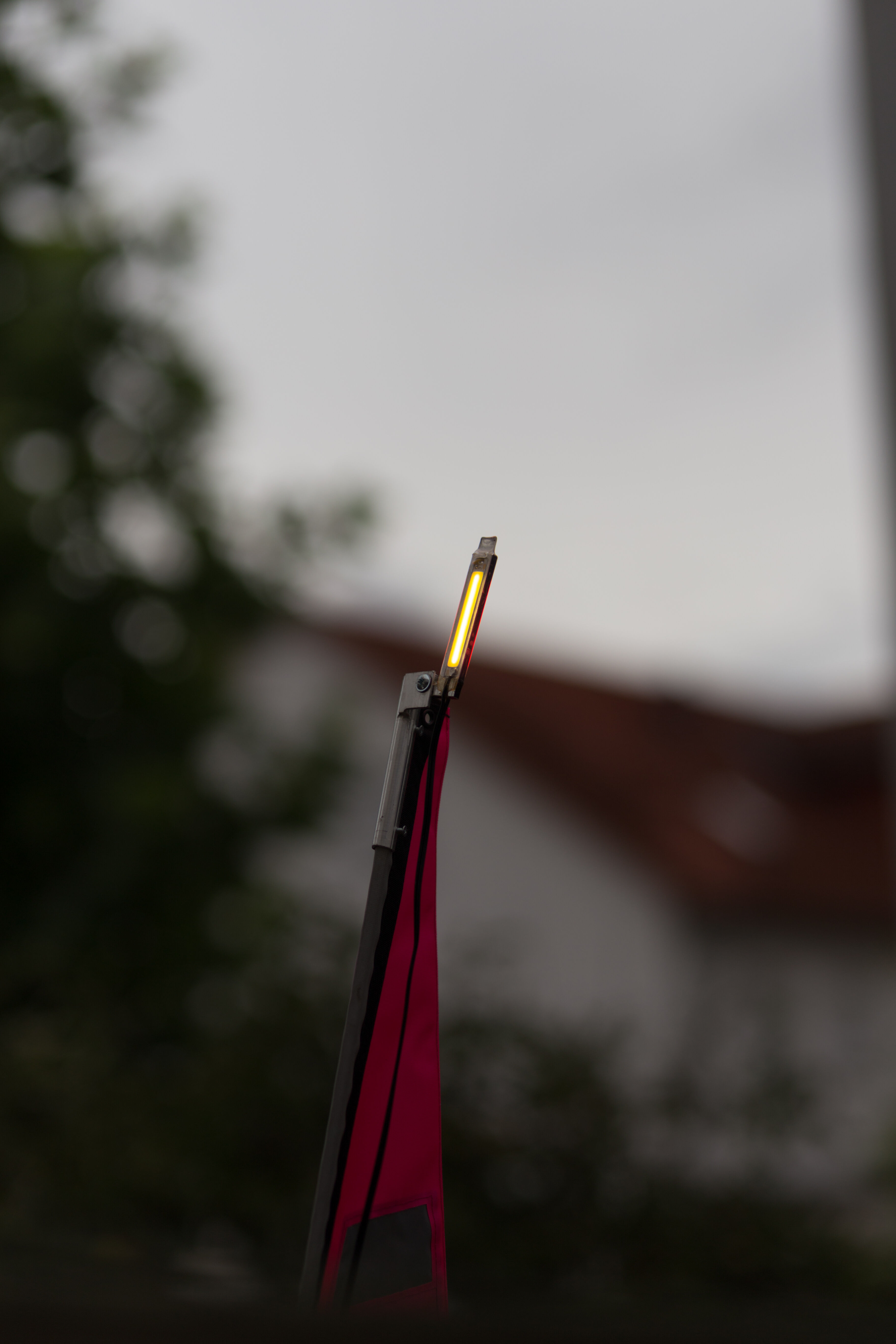
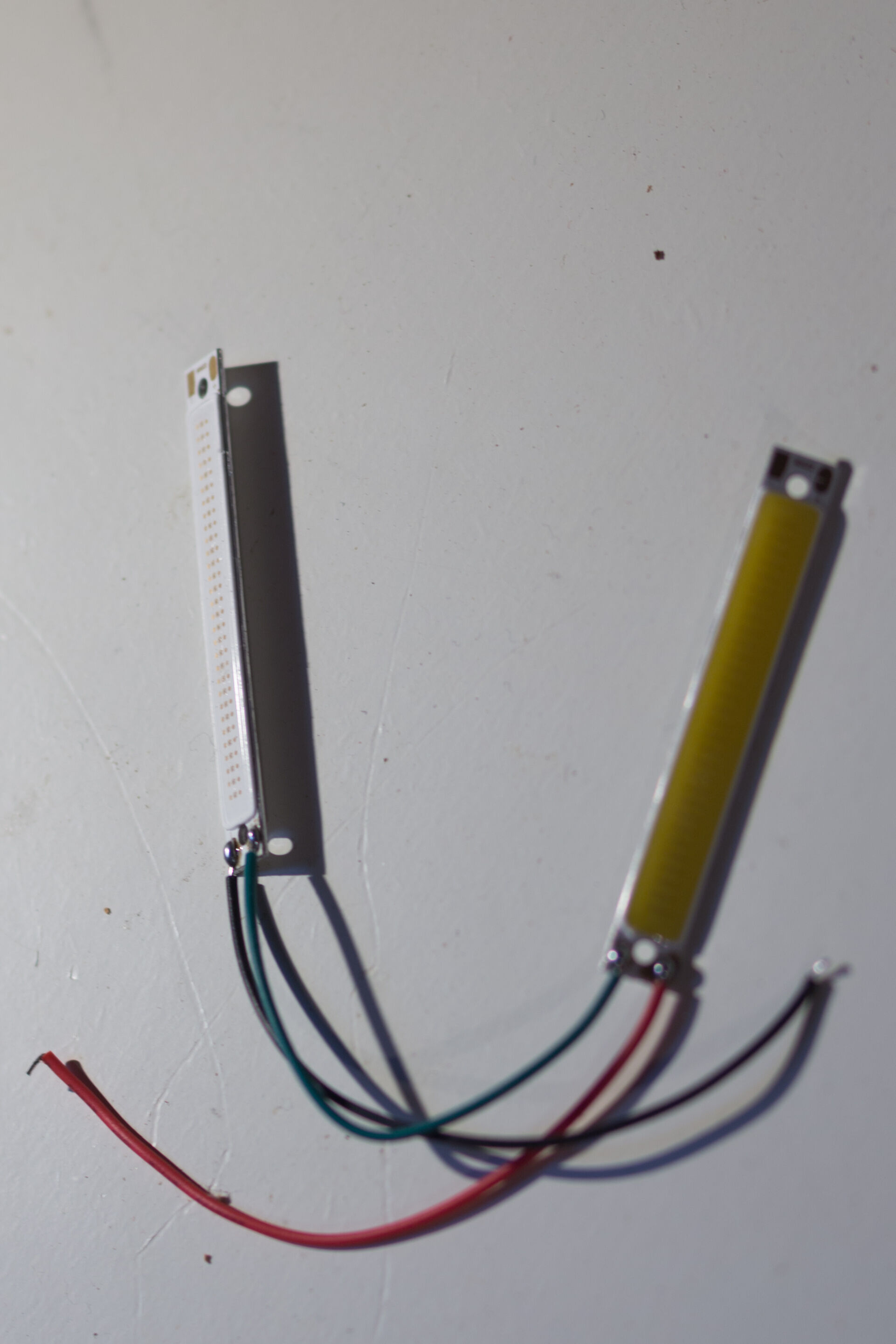
Long story short: I over-engineered the whole thing and now I want to show it off. My choice of LEDs are 4cm long chip on board bar-shaped LEDs. I got one white and one red so I would be visible both from front and back. Both are 300mA versions so I can connect them in series. Because the voltage regulator promised PWM brightness regulation so I added a controls to the handlebar to remote control brightness and allow for blinking. The LEDs are glued to a hand-milled aluminum carrier and covered by transparent heat-shrink tubing against the weather. The control electronics are also covered by heat-shrink tubing. The switch should be weatherproof given that it’s one meant for motorcycle use. Power is supplied by a weatherproof box with four 18650 lithium batteries. Remember that the pictures below are taken in daylight — When it is dark the light is pretty bright and the movement of the flags makes it even more visible.
Nevertheless I tend to drive way more defensive on the recumbent than on the upright. I wonder whether it’s more safe than the upright due to my defensive driving or still more dangerous because it’s so low.
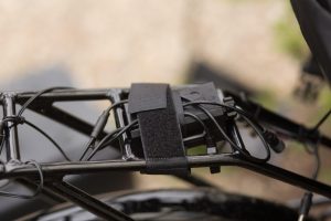
Arduino and battery pack attached to the bike rackBattery pack and arduino on bike rackFlag with light from the back
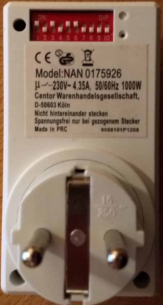
I really wanted to use these cheap RF switches with Homeassistant. Unfortunately the rpi-rc library needs an integer number to know what to send for the switch to switch. I didn’t have an RF receiver so here’s a script that can convert between the 10 bit dip switch setting on the back of the plug and the integer needed for rpi-rc:
!/usr/bin/env python3
 import argparse
 def codify(code):
     return code.replace("0", "00").replace("1", "01")
 parser = argparse.ArgumentParser(description='Sends a decimal code via a 433/315MHz GPIO device')
 parser.add_argument('code', metavar='CODE', type=str,
                     help="zeroes and ones from the dip switch ('up'=1, 'down'=0)")
 args = parser.parse_args()
 code= args.code.replace('1','3').replace('0','1').replace('3','0')
 code_off= codify(code+'00')
 code_on= codify(code+'01')
 print("off: {}".format(int(code_off, 2)))
 print("on:  {}".format(int(code_on, 2)))</pre>
run it like so (with zeroes and ones for the dip-switch setting, example for the pictured switch) to get the integer codes for on and off:
python dipswitch_convert.py 1010110000
 off: 1115472
 on:  1115473
afterwards you can use the integer codes for on and off with the integrated scripts in rpi-rc (or home-assistant):
rpi-rf_send -g 5 1115472
[:de]
Ich benutze einige dieser billigen Funksteckdosen mit Mäuseklavier (dip-switch) auf der Rückseite. Die will ich natürlich auch mit homeassistant benutzen. Leider braucht die von homeassistant verwendete rpi-rc bibliothek einen Integer als Code. Da ich keinen Konverter finden konnte hier mein quick-n-dirty Konverterscript:
 !/usr/bin/env python3
 import argparse
 def codify(code):
     return code.replace("0", "00").replace("1", "01")
 parser = argparse.ArgumentParser(description='Sends a decimal code via a 433/315MHz GPIO device')
 parser.add_argument('code', metavar='CODE', type=str,
                     help="zeroes and ones from the dip switch ('up'=1, 'down'=0)")
 args = parser.parse_args()
 code= args.code.replace('1','3').replace('0','1').replace('3','0')
 code_off= codify(code+'00')
 code_on= codify(code+'01')
 print("off: {}".format(int(code_off, 2)))
 print("on:  {}".format(int(code_on, 2)))
Ruft man es mit der Einstellung des Mäuseklaviers aus dem Bild als Nullen und Einsen auf:
python dipswitch_convert.py 1010110000
 off: 1115472
 on:  1115473
Bekommt man die Integercodes für an und aus, die man mit Homeassistant oder der rpi-rf Kommandozeile verwenden kann:
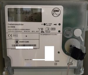
[:en]Derzeit werden in Deutschland Stromzähler durch “Smartmeter” ausgetauscht. Die Smartmeter sind gerade smart genug, den Momentanverbrauch anzuzeigen. Damit sie das auch tun, muss man mit einer Taschenlampe eine PIN (PIN gibt es per Post vom Netzbetreiber) in das Smartmeter leuchten. Keine Ahnung, wer sich das Verfahren ausgedacht hat, Viel billiger als eine Folientastatur für eine Pin kann das kaum sein und es ist definitiv weniger smart. Vorne am Smartmeter gibt es eine Infrarotschnittstelle, über die man den Momentanverbrauch und den aktuellen Zählerstand gefahrlos (=Galvanisch getrennt) digital auslesen kann, nachdem die Pin eingegeben wurde.
Leider sind typische Leseköpfe für ihren Inhalt schweineteuer. Ein mit 45€ noch vergleichsweise günstiger kommt z.B. von Weidmann Elektronic. Typischerweise ist in so einem Lesekopf aber auch nur ein USB-Seriell Wandler und je nach Ausführung ein Fototransistor und eine IR-LED oder sogar nur ein Fototransistor verbaut.
Wenn man schon eine serielle Schnittstelle hat (z.B. USB-Seriell Wandler herumliegen oder einen Raspberry Pi…) kann man den Lesekopf auch für wenig Geld selbst bauen. Ich habe mich von diesem Post inspirieren lassen.
Kabel (lang genug um vom Lesenden Gerät bis zum Smartmeter zu gehen. Bei mir steht der Raspberry PI direkt unterm Stromzähler)
Aufbau des Sensors:
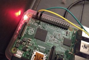
Der BPW40 kann direkt zwischen GND und RXD des an den GPIOs eines Raspberry Pi (oder eines USB-Seriell-Wandlers) angeschlossen werden. Für Raspberry Pi 3 sollte man erstmal im Vorfeld das Bluetooth-Modul deaktivieren, da dieses auch am seriellen Port angeschlossen ist.
Bei der Richtung des Fototransistors kann man nicht viel falsch machen: Ich habe den Sensor gleich mal versehentlich falsch herum angeschlossen, dem Raspberry Pi schadet das nicht, da schlimmstenfalls RxD auf GND gezogen wird (und dafür ist RxD ausgelegt). Auch der Sensor sollte vom schwachen Pullup an RxD nicht kaputt gehen können. Ist der Sensor falsch herum angeschlossen, empfängt man halt natürlich nix.
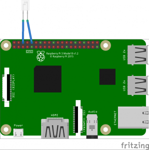
Verdrahtung des BPW40 mit dem Raspberry Pi
Anbringen am Stromzähler
Bei mir steht der Raspberry eh in der Nähe des Stomzählers. Den BPW40 habe ich am Kabel festgelötet und mit etwas Isolierband an einem kleinen Magneten befestigt. Die Metallscheibe am Stromzähler bei der Infrarotschnittstelle ist magnetisch, damit man den “Lesekopf” auf diese Weise dort anbringen kann. Hier ein paar Bilder des Aufbaus:
Anschluss des BPW40 auf dem Raspberry Pi
Seitenansicht “Lesekopf”: Isolierband verbindet BPW40 mit Haltemagnet. Dazu etwas Schaumstoff um die Pins gerade zu halten.
Draufsicht BPW40 mit Magnet am Stromzähler befestigt.
Ausblick: Setup auf dem Raspberry Pi
Um den Lesekopf zu aktivieren, muss man erstmal den seriellen Port nutzbar machen. Für Rasberry Pi 2 heißt das: raspi-config konsolenprogramm ausführen, darin folgende Schritte: Interfacing Options -> Serial: Would you like a login shell to be accessible over serial: NO -> Would you like the serial hardware port to be enabled: YES. Für Raspberry Pi 3 sollte man zusätzlich im Vorfeld das Bluetooth-Modul deaktivieren
Nach dem Reboot kann man dann mit cat /dev/ttyAMA0 mit etwas Glück die ersten Daten reintröpfeln sehen, wenn man den Lesekopf vor die Sendediode des Stromzählers hält. Falls nicht, lohnt es sich ein Terminalprogramm aufzurufen und dort die richtige Baudrate, den richtigen Port und den richtigen Übertragungsmodus zu wählen (typischerweise 9600 8n1). Ich habe minicom verwendet, das kann mit apt install minicom installiert werden, z.B. hier gibt es eine Kurzanleitung.
In einem weiteren Schritt braucht man dann eine Software, die das Binärkauderwelsch aus dem Stromzähler dekodieren kann, ich habe node-red zusammen mit dem node-red-contrib-smartmeter-Modul verwendet, um die Daten in ein bereits laufendes graphite backend zu füttern und mit Grafana zu visualisieren. Am Ende bekommt man schöne Grafen des Stromverbrauchs. Man sieht gut dass unsere Grundlast mit um die hundert Watt ziemlich hoch ist. Die hohen Spikes sind der Backofen.
Wenn ich dazu komme mache ich noch einen Post über das Setup von nodered und graphite/grafana.
[:en]The wife now also starts a blog. Time to play: This blog here is still set up the old-fashioned way, php and mysql running on the web server. But setting up a wordpress for her gives me a welcome excuse to play with docker.
So there you go:
For the simplified creation of vhosts for docker containers I set use a trio of containers using a slightly-adapted version of this docker-compose.yml:
nginx as reverse-proxy
jwilder/docker-genfor automatic creation of v-hosts based on container environment variables: simply pass -e VIRTUAL_HOST=your.domain.com and this container adapts the vhosts config for nginx accordingly.
jrcs/letsencrypt-nginx-proxy-companion to also automatically fetch a letsencrypt certificate and enable ssl for the new vhost..
For the wordpress instance I run an adapted docker-compose.yml for the usual container pair of wordpress and mysql. Apart from keeping the wordpress instance in a directory volume (for easy fiddling) i added the following modification:
This enables automatic creation and sslification of the vhost in the nginx reverse proxy.
The nginx-reverse-proxy solution really makes it very convenient to just spin up a new container and immediately use it with a valid SSL certificate. Definitely worth the time for initial setup – it does not take longer than setting up SSL manually but you only have it once to get SSL for all vhosts.[:de]Die Frau setzt jetzt auch ein Blog auf. Da gerät man schnell ins Spielen. Während dieses Blog hier noch altbacken mit php und mysql auf dem Server läuft habe ich für das neue ein Team aus Dockercontainern aufgesetzt:
Für die automatische Einrichtung ein Trio aus Containern basierend auf diesem compose file:
nginx als reverse-proxy
jwilder/docker-gen zum automatischen erstellen passender vhost-konfigurationen für den reverse proxy. Einfach die passende Umgebungsvariable -e VIRTUAL_HOST=your.domain.com setzen, und nginx richtet den passenden Vhost ein und leitet ihn auf den exponierten port weiter.
jrcs/letsencrypt-nginx-proxy-companion zum automatischen Abruf passender Letsencrypt SSL zertifikate für die erstellten Vhosts.
Darunter dann ein angepasstes docker-compose.yml für das übliche Paar aus WordPress-container und *sql-container. Hauptanpassung (neben dem verschieben des WordPress-folders auf ein directory volume für einfachere anpassungen):
Damit funktioniert dann auch das automatische Erstellen eines vhosts.
Die Nginx-reverse-proxy-lösung macht es supereinfach neuen Containern gleich einen funktionierenden Vhost mit SSL zuzuteilen. Dabei braucht man fürs Aufsetzen auch wenig länger als für die manuelle SSL-Konfiguration eines einzelnen Vhosts. Sobald man den zweiten Container mit SSL versorgen möchte oder einen neuen Vhost hinzufügt hat man diese Zeit wieder drin.[:]
[:en]Zur Deutschen Version des Textes.
I use homeassistant as a front-end for home automation. It is really hackable, written in python and comes with support for a lot of devices. I chose it initially because it has mysensors support.
Last year I needed a solution for controlling roller shutters. Sadly most manufacturers that market in Germany are pushing their own proprietary solutions for home automation. While homeassistant supports a few of those via the proprietary gateways of the manufacturers, the gateways themselves can be very pricey. Additionally the installed roller shutters were belt-operated and the shutter was mounted in a steel case above the window. Unfortunately the hatches giving access to the roller shutter were so small that I ditched my initial plan of mounting a tube motor in the shutter roll.
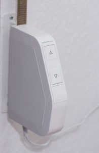
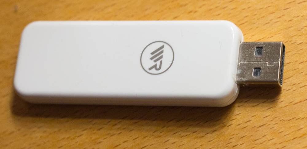
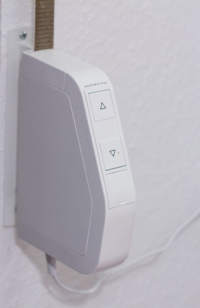
Finally I found that german manufacturer Rademacher sells wall-mounted belt motors for Roller shutter operation (“Rollotron”). Some of these can be remote-controlled via “duofern”, a proprietary remote control protocol by the manufacturer. While homeassistant does not come with out-of-the-box support for this protocol, the Perl-based FHEM home automation project has support for these blinds via a usb stick sold by the manufacturer.
I loathe perl, therefore I ported the rollotron-related sections of the GPL-licensed FHEM implementation to python. My python port can currently be found as pyduofern on bitbucket.
There is some documentation on how to get it to work with homeassistant in the subdirectory examples. Luckily the RF communication goes both ways, so homeassistant displays the current position of rollershutters regardless of whether they have been moved with manual controls or via homeassistant.
The whole thing is work in progress – in order to get it natively into homeassistant the next step would be to add it to pypi, but before I do that I would rather have it working with asyncio, because that is the way to do it for homeassistant.[:de]
English version of this post here Homeassistant ist mein Frontend der Wahl für Hausautomatisierung. Schönes Interface, in Python geschrieben, und leicht anzupassen. Angefangen habe ich damit wegen des Mysensors-Supports.
Letztes Jahr ging es dann daran, die Rolladenmotoren auszusuchen. Leider versuchen die meisten Hersteller, ihre eigenen proprietären Lösungen in den Markt zu drücken. Homeassistant unterstützt zwar ein paar dieser Lösungen, aber man muss sich trotzdem noch oft ein schweineteures Gateway anschaffen, um mit den Komponenten reden zu können. Für mich war es zusätzlich schwierig, weil die installierten Rolläden mit einem Gurt daherkamen und der Rolladenkasten aus Stahlblech ist und so eine winzige Öffnung hat, dass es nicht mit vertretbarem Aufwand möglich ist, Rohrmotoren zu installieren.
Am Ende habe ich mich dann für Rademacher entschieden. Aus Faulheit: Gurtwickler für Einbau- oder Aufputzmontage mit Möglichkeit zur Funkfernbedienung. Die Entscheidung fiel auf sechs RolloTron Standard DuoFern. Homeassistant unterstützt zwar Duofern nicht von Haus aus. Die Perl-basierte Hausautomatisierung FHEM unterstützt aber das Duofern Protokoll mithilfe eines preislich akzeptablen USB-Sticks von Rademacher.
Ich traute mir zu, den Perl-Code für Homeassistant zu portieren. Nach ein paar Wochen hatte ich die Rolladensteuerung mit Homeassistant dann im Juni 2017 am Laufen. Pünktlich, um im Sommer die Rolläden nach dem Stand der Sonne zu fahren und das Haus schön kühl zu halten. Das Ergebnis findet sich als pyduofern auf meinem github.[:]
I keep forgetting how to do this so I’m finally gonna write it down. Synology DSM does not allow you to define arbitrary firewall rules. I especially want to define more paranoid firewall rules attached to openvpn connections. Sadly the GUI does not know about selective firewall rules for these so I had to do it myself. Synologys openvpn client calls
on disconnect. To define my own firewall rules I figured I would have to add to these two scripts. Unfortunately synology only sets its firewall rules some time after the scripts have run. So when I just add my own firewall rules to the two scripts, they are overwritten seconds later by synologys firewall. My solution is the following: at the end of the synology scripts
ovpn-up
and
ovpn-down
I add my own firewall setup script via:
# above here is synologys original code
# save the return code of the synology ip-up/down logic
returncode=\$?

# call my script and send it to the background
nohup /opt/bin/iptables.sh &

# pass the original return code to the calling process
exit $returncode
In my own firewall script I begin with:
sleep 10
before I proceed to remove the synology firewall rules and replace them with my own.
WARNING: DSM Updates may overwrite your custom settings. Whenever you update DSM make sure that your settings are preserved.
The Doctor Who intro features a vortex clock. Find it on youtube here (left of the two clips). I went through some pain to vectorize it in halfway decent quality in preparation of building a Doctor Who themed wall clock. In case anyone else wants an SVG version here is my amateur attempt. I know a lot could be done to make the SVG way smaller (probably the image could easily fit into 1/10 the size). My main goal was to get something that prints decently with a laser printer to iron on an aluminum plate, and this SVG is sufficient for that purpose.
Ever since I saw the microtype manual, I wanted to have something similar. The amazing thing about it is that you can switch on and off different microtype options and observe the resulting PDF output,
I now found the package ocg-p which allows to generate pdfs with dynamically switchable layers similar to the above. I built a demonstration which switches between a greek epigraph and its translation by clicking.
The code I used is the following, you can find the resulting PDF output here. The dynamic features only work in dedicated PDF readers (try opening with Acrobat):
\tikzset{external/export next=false}

\begin{tikzpicture}[node distance=3cm,every state/.style={fill=green!20},auto]
\begin{ocg}{edges}{ocedgesid}{1}
\draw[opacity=0] (-5,4)--(0,0);
\end{ocg}
\begin{ocg}{english}{german}{0}
\node[anchor=south east] at (0,0) { \toggleocgs{greek german}{I know that I know nothing}};
\node[anchor=north east] at (0,-0.2) { \toggleocgs{greek german}{\textit{Socrates}}};
\draw (-2,-0.1)--(0,-0.1);
\end{ocg}
\begin{ocg}{greek}{greek}{1}
\node[anchor=south east,font=\selectlanguage{polutonikogreek}] at (0,0) { \toggleocgs{greek german}{Οἶδα οὐκ εἰδώς.}};
\node[anchor=north east,font=\selectlanguage{polutonikogreek}] at (0,-0.2) { \toggleocgs{greek german}{\textit{Σωκράτης}}};
\draw (-2,-0.1)--(0,-0.1);
\end{ocg}
 [:de]Es ist schon länger still geworden hier im Blog – Derzeit arbeite ich viel am OpenBikeSensor mit.